Update @ Sat 17th Feb — The source code for this project is now available from my GitHub repository.
Update @ 8th Mar 2018 — Currently the DHCP option doesn’t work (timeouts/WDT-resets). The IP address of the W5500 will need to be set manually in the code (thanks to “1rabbit” for the heads-up on this issue).
Update @ Fri 5th April 2019 — Here’s the simple ESP32/W5500 NTP client example. The ESP32 wiring is even easier (no buffer transistor required).
A few months back I pointed readers to an article by Frank Sautter on adding an Ethernet port to the ESP32 which I found quite interesting. It reminded me that I’d been playing around with a Wiznet wiz820io board a while back on an older PIC-based project, so I pulled it out of the parts drawer and started fiddling with trying to get it working with an ESP8266 module. There were some signs of life, but it was so flaky that I really didn’t quite know whether I had dodgy hardware or whether my graft of the ESP8266 code from the W5100 library to the W5200 library was just crap (the latter being a very strong possibility). It had whetted my appetite though, as I was looking for a means to interface an ESP module to my LAN as an ESP-Now gateway.  So I ended up getting one of the (cheap) newer W5500 modules (the one with the yellow pin header and the “PWOER” LED label)‡ which are popping up all over the place at the moment at about $4 shipped (click on the picture on the right to see the full-size image of the board). The W5500 handles more sockets than the older versions of the chip and is generally recommended for newer designs (it’s a little cheaper, too).
Although the W5500 needed a little tweaking to get going, there weren’t any serious issues with either the hardware or the software and it didn’t take too long to get it working. One issue (which is actually an ESP problem, not a W5500 one) is that the chip-select for the external SPI is actually routed via GPIO15 and, as we pretty much all know from experience by now, that’s one of the “magic” pins at boot-up/reset which changes the way that the ESP8266 behaves. In fact there’s a pull-up resistor on the W5500 (and, as far as I know, all of the other Wiznet modules) CS line which will cause the ESP to drop into programming mode if the W5500 CS line is simply connected directly to GPIO15. The solution to that is quite easy — put a PNP transistor buffer (configured as an emitter follower) between the two. 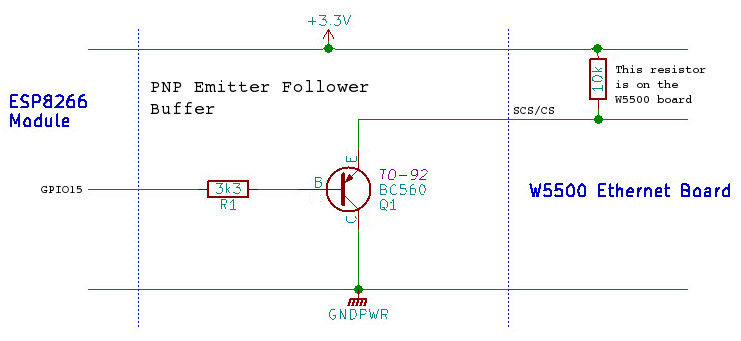 Because of the pull-up on the W5500 board, you don’t need an emitter resistor, but you do need to add a base resistor of somewhere in the region of 3k3 between GPIO15 and the transistor’s base (and the collector of the transistor goes directly to ground). Any small-signal PNP transistor, such as the BC560 or 2N3906 should work in this situation; it’s not that critical. This fix should work for pretty much any SPI connected peripheral board …but you might have to add the emitter resistor if the target board doesn’t already have a pull-up.
The second hardware requirement is that we need to dedicate another, non-SPI GPIO as a reset driver for the W5500. On my test board I used GPIO5. This allows us to hold the W5500 in reset until the ESP has completed it’s own housekeeping and is ready to bring up the network connection. So, with that addition, the pin connects between an ESP8266 and the W5500 are:-
The pin numbering for the NodeMCU boards is given on the left, with the standard ESP8266 GPIO numbers in the centre column. In addition to the data pins shown above, you need to connect ground and either +5v -or- +3v3. The W5500 board has its own, on-board voltage regulator, so a +5v supply is okay, but sharing a 3v3 supply with the ESP8266 is a more likely scenario in our case (the data pins on the W5500 are 5v tolerant, by the way).
On the software side, I ended up using the Wiznet Ethernet Library for the Arduino 1.5.x IDE. It hasn’t been updated in a while …but the last updates were to add the ESP8266 hooks into the code. There are good instructions in the README.md file on how to install and use it, but –don’t– uncomment the “#define WIZ550io_WITH_MACADDRESS” line referred to in those instructions. The normal, cheap W5500 boards do -not- have a built-in MAC address and you must set one manually in software before you can use them.
All in all, it really was quite easy to get the W5500 ethernet board not just connected to my LAN, but also talking to my MQTT broker to both publish and subscribe. Sometime in the next couple of days I’ll try to get around to sanitizing my code to the point where I can throw it up on GitHub as a simple example, but even before then, I’d say this is a safe enough purchase[¹] for anyone who wants to muck around with a wired connection to their ESP8266; you’re not going to break the bank if it doesn’t work as expected.
[¹] – Careful though! If you’re reading this in mid February, it’s Chinese new year, so everything will be closed down for the next week or so …even longer delays. 😦
[‡] – Link provided as a convenience. This is where I bought mine. I have no relationship with this seller, other than being a satisfied customer.

Thank you very much for this detailled and well-written article!
What I would like to know:
Will the WiFi of the ESP8266 still be fully usable or will it somehow be affected
by the addition and usage of the Ethernet parts?
LikeLike
Rick,
The WiFi is still operating as normal. In fact the ESP8266 still gives priority to the WiFi, while the dedicated microprocessor inside the W5500 handles the low-level processing of the wired network traffic.
One of the things to remember about this configuration is that we’re not asking the ESP to do too much heavy lifting. As it stands, the example code is simply passing (relatively infrequent) messages to a single MQTT server. It’s nothing like the ethernet port on your Linux box, which is handling multiple services on multiple ports (DNS, NTP, SSH, HTTP, DHCP, etc).
You still need to make sure (as with anything you’re writing for the ESP8266) that you leave the processor enough free cycles to handle the WiFi stack, but other than that, it should be quite possible to add services to the W5500. The Ethernet or Ethernet2 libraries available online (not the cut-down version in the lib directory of my source) has several complete reference programs under the “examples” directory which should be fairly easy to implement (for instance, adding an NTP client to ensure your gateway always has the correct time).
The next iteration of this project is an ESP32 version (the prototype hardware is already working) which will probably include some extra bells and whistles like NTP …if “real life” would just let me have some free time to play. 🙂
-John-
LikeLike
Thanks a lot for all your explanations, John!
As you are obviously 100x more an ESP and network expert than I am, do you have by any chance experience with getting an ESP8266 to connect to a WPA2 Enterprise network (with a certificate, not user name/password)? I read that this can be done, but I only find some bits and pieces and no real example…
LikeLike
Sorry Rick, that’s way outside my comfort zone. 🙂
As a very broad, general statement from someone who doesn’t know …I have also heard that things like this can be made to work, but don’t generally leave enough space for any useful applications.
LikeLike
Thanks for the explanation of setting up W5500 and Nodemcu. I can compile and upload the sketch but I fail to set the IP address of the W5500 Ethernet port. The serial monitor shows “Ethernet IP: 255.255.255.255”. Your advice is much appreciated. Thanks.
LikeLike
Hi Richard,
This is a pretty good indication that your ESP isn’t actually talking to the W5500 at all. Double check all of your connections for continuity, especially the CS line (also check that your CS buffer transistor is a PNP, -not- an NPN and check that you can see approximately 10k between the emitter and the positive rail). If everything there looks good, make sure you also have a good, stable power supply to the W5500 board.
It sounds like this is a very basic issue, so it (hopefully!) shouldn’t be too difficult to solve. Let us know how it goes.
-John-
LikeLike
Thank you for your advice. There was a misplaced color wire. It shows an IP address now but it is just a random number. The PNP transistor is 2SA733 and a stable 5V power supply is used. Your attention is appreciated. Thanks.
LikeLike
Richard,
Great, sounds like you’re getting there. The latest results still sound like a hardware issue, though. Your ESP and W5500 are trying to talk, but something is out of sequence, so now you’re looking at an issue with the reset or CS lines (possibly even the clock line). I’d do a continuity check on your wires (or just replace them, one by one, testing in between) and double check your transistor connections (the 2SA733 should be perfect for this application, but it does have a slightly unusual pin-out, according to the data sheet — E,C,B, looking from the front).
If you’re unsure of the transistor, you could always replace it with a non-inverting buffer, such as a 74LS07 (or, just for testing, you can get rid of it completely and add a long delay, maybe five or ten seconds, after start up to give you time to manually insert the CS line into the NodeMCU pin socket).
Good luck!
-John-
LikeLike
Thanks for your advice. There was also a ground wiring issue. I am getting core dump after showing a random IP address now. I used a transistor tester to test the transistor and it was fine. I checked the SPI on the Nodemcu using a TFT LCD display and it was fine too. When I disconnected CS, CLK, MISO or MOSI line, the core dump stopped. The RST line did not make any difference either connected or disconnected.The LED on the Ethernet socket showed traffic on the Ethernet cable.
LikeLike
Richard,
You may have answered your own question with this one. If you disconnect the CS/CLK/MISO or MOSI, you’re effectively disabling the SPI connection completely. RST is effectively one way …the ESP is meant to hold the W5500 in reset until it has completed its own housekeeping start-up tasks. It sounds as though that isn’t happening and the W5500 is overwhelming the ESP with SPI traffic before it is ready to deal with it.
While the other pins are “set in stone” (those are the pins which are defined in the hardware for the SPI interface), the reset pin is not. You can move the reset onto any free GPIO (although it makes sense not to use either GPIO-0 or GPIO-2) and just change the define for RESET_P in espnow_gw.h to match.
Best wishes,
-John-
LikeLike
Great work, amazing. I am trying same thing with ESP32 dev board. I am using gpio 5 as CS pin and GPIO 4 as w5500 reset. Not using buffer, straight connection.
I am facing problem that it is not working at all. I can see link led (yellow) steady glow also green led blinks as it shows some data transmit but with Ethernet2 lib DHCP printers i am not ip address at all. Even nothing after long wait it gives error failed
LikeLike
Hi Suman,
I’m in the middle of doing the same thing (if only real-life would grant me some spare time to work on it). The ESP32 code is very different and, of course, the hardware connections are different, too.
My notes on the connections I’m using are:-
VSPI MOSI – GPIO23
VSPI MISO – GPIO19
VSPI SCLK – GPIO18
VSPI CS – GPIO5
RESET – GPIO26
You’re right; the CS line doesn’t need a buffer to work with the ESP32, so a couple of components less.
I chose GPIO26 for the reset because it didn’t have any pull-up/down configured (GPIO4 has an internal pull-down) and because it didn’t clash with any other peripheral pins that I want to use in addition to the W5500 (I’m planning on using the I2C bus and on adding a couple of WS2812 LEDs for some see-at-a-glance debug indicators).
I had to use an explicit call “Ethernet.init(5)” to get the CS to work on the ESP32 (setting pinmode as output isn’t enough). There was also a fairly recent change to the SPI library which hadn’t made it into the mainstream library when I started working on this, so I needed a local version of the (new, updated) library.
Overall, I think I made a mistake in trying to import my original ESP8266 project; I should have started off with a blank slate for the ESP32. I would have saved myself a lot of time. 🙂
Right now, I only have the initialization and connection to the MQTT server working, but I’ll sanitize the code and try to get it up on GitHub sometime in the next couple of hours.
Let us know how it goes,
-John-
LikeLike
Here we go:-
https://github.com/PuceBaboon/ESP32_W5500_GW
LikeLike
[…] the past couple of days, in the course of answering questions on the popular article on adding an ethernet port to the ESP8266, I found myself putting up a link to some new code for a work-in-progress project which simply […]
LikeLike
Thanks for the great tutorial.
As u instructed i have connected the NodeMCU/esp8266 to the ethernet module along with the specified circuit. But when i am trying to assign the IP, using the command “Ethernet.begin(mac, ip);” and printing the serial output of “Ethernet.localIP()” it is giving out the error “IP unset”. And when i remove the CS pin the output in “255.255.255.255”.
I even tried with the Ethernet Shield, but it is directly giving the output “255.255.255.255” even when the CS pin is attached. Please help
regards
Srivatsa
LikeLike
Hi Srivatsa,
You might want to go through a couple of the previous comments (above). The 255 issue is a good indication of a hardware problem. Your ESP8266 and the W5500 aren’t actually talking to each other at all. Check that you have a good, common ground connection for both boards and that the positive supply is good, too (make sure you don’t have +5v going to +3v3, or vice versa). After that, you need to check each individual bus connection, one by one, to ensure that all of the interconnects are good (swap one wire at a time with a known good one and test between each swap). Ensure that your transistor is good and that you have the pins correctly identified and connected. If you suspect the transistor buffer, you can add a long delay (say 10-seconds) right at the very start of the setup() code, to give you time to manually connect a wire between GPIO15 of the MU and the CS of the W5500, instead.
Let us know how it goes,
-John-
LikeLike
Thanks for the support and guidance, John.
You pointed out the error perfectly, there was jumper wire creating the problem. Now i am able to get the IP address(static) for the MCU, and print via serial monitor.{i have set my system IP in the same network as of MCU}
But, when i am trying to ping through the cmd prompt, i am getting the reply “TTL expired in transit”. I have double checked all the connections, but found no continuity issue.
I believe when MCU has got the IP, it should be able to ping back (i have cross checked the program with ArdinoUNO with Ethernet shield and successfully got the IP and also the ping was successful with the same IP settings as before). Any help would be greatly appreciated. {my current need is to read data via Ethernet and transmit via WiFi, so i believe NodeMCU would be great, please correct me if I’m wrong}.
regards,
Srivatsa.
LikeLike
Srivatsa,
Great to hear we got one step forward. 🙂 The TTL expired error sounds as though a router is getting involved in the transaction, which should not be the case if both of your machines are on the same subnet …which points to a typo in the IP address which you’ve assigned to the W5500.
Your plan of reading data from the W5500 and re-transmitting via WiFi sounds fine. Check the Arduino Ethernet library examples directory, there’s at least one “echo” example in there which should be fairly easily adapted.
-John-
LikeLike
Hey John…
All credits to you and your awesome hack. It finally worked with some changes in program. {there was no typo in IP address, however i had to change the Ethernet library to make it working. I couldn’t get the logic of why or how, but still I’m happy that it’s working.} You really saved my time and money.
Thanks a lot. 🙂
Regards,
Srivatsa.
LikeLike
Srivatsa,
Great news! Glad to hear you persevered and got it working.
If you have a spare moment, please let us know (in the comments) what version you changed to; it could help someone having a similar problem in the future.
All the best,
-John-
LikeLike
Surely i would share all the details. Mainly i switched from “ethernet.h” to “UIPethernet.h” after making some changes in different .h and .cpp files. I will share my git repository within a week (need to remove some of the company’s proprietary data). {i still don’t know the reason why Ethernet.h was failing, even with ArduinoUno+w5500 module, but the code is working perfectly with Uno+shield!}
regards,
Srivatsa
LikeLike
Hey John,
Extremely sorry for the delayed reply, got busy last month. I have uploaded the code on my git repository https://github.com/srivatsaks/UIPEthernet_edtd , and have mentioned this link on the hardware folder (Do guide me further where to acknowledge you in this regard, as it is my first attempt over git). Please verify and let me know any issue that arise.
And i am currently working on SNMP over NodeMCU, i needed some help with string handling. Could you please share your contact detail, so that i can share my issue.
LikeLike
ENC28J60 != W5500
LikeLike
Sorry for giving out wrong information. It was basically due to my limited knowledge on both the hardware.
(programs are running smoothly with ENC28J60, i will update it further after trying it with W5500 module.)
LikeLike
Hi, thanks for this page and the tutorial. There is very little information around on how to get an ESP8266 working with an ethernet board, after all it already has wifi for connection. Unfortunately I have applications that can’t or won’t use wifi and it needs the larger programming space and ram, without going to the larger arduinos.
So I had been struggling with getting the ethernet board (W5500 with yellow connector) going using the esp8266 core for the arduino ide. The compiler was using the older(?) ethernet library that came with the esp core by default. This just would not work. I spent many hours going through the various library scripts, but could not get it to work. Also the newer ethernet library used for all the other arduinos (not esp) worked fine and had extra routines. I eventually found a solution and thought you and others might be interested. I may even try and get it implemented in respective gits.
The solution was to first delete or move the ethernet library in the esp core. If you move it you can restore it or reload the core through board manager, if this doesn’t work.
On my PC the esp ethernet library was in –
C:\Users\Tony\AppData\Local\Arduino15\packages\esp8266\hardware\esp8266\2.5.2\libraries\ .
I moved the whole Ethernet folder. This will force the compiler to use the other arduino ethernet library.
A file in the arduino ethernet library will need a small modification to work correctly with the esp. You need to modify Ethernet.cpp , on my PC it’s located at
C:\Program Files (x86)\Arduino\libraries\Ethernet\src\ .
You need to change after line 85 –
#if ARDUINO > 106 || TEENSYDUINO > 121
to
#if defined(ARDUINO_ARCH_ESP8266)
W5100.setIPAddress(ip.raw_address());
W5100.setGatewayIp(gateway.raw_address());
W5100.setSubnetMask(subnet.raw_address());
#elif ARDUINO > 106 || TEENSYDUINO > 121
Save it and it should all work. This will allow the ethernet library to work with the esp core and all the other cores. I’ve only tested with esp and arduino.
Unfortunately any updates to the esp core or arduino core will probably overwrite the changes.
This works with GPIO15 and the transistor buffer, or you can change the SCS pin to any other available pin using the Ethernet.init(15); instruction, seems the default is GPIO15 for an esp8266.
LikeLiked by 1 person
Hi, thanks for the very useful info, it worked great for me and I can use Arduino-style ethernet and ESP WiFi at the same time.
Its running well for me using a WeMos-mini and a USR-ES1 module (W5500 chip).
Everything i’ve tried seems to work OK, even DNS lookups. I did sprinkle a few yeild() statements in the default arduino library and so far have had no issues.
LikeLike
Thank you Tony for your valuable information. Your solution works. Thanks.
LikeLike
I changed the CS pin GPIO connection as suggested by Tony. This configuration worked without the transistor. The Ethernet module 3.3V was provided by the Nodemcu which was powered by USB connection from a laptop. Tony, thanks again.
LikeLike
Using GPIO0 as CS could allow to the use of “shared SPI mode” re-using lines already used by Flash chip, so you don’t end up using precious GPIOs (except for GPIO0 and possibly reset).
I’ll test it as soon as I get the boards I ordered.
LikeLike
Hi, Great idea. I want to use the W5500 module with TASMOTA software. Mean to use all the esp8266 tasmota features (webserver mqtt conf etc) BUT WITH ETHERNET WIRED CONNECTION. Can someone help me with this?
LikeLike
Hello! I follow your post and now I can connect internet for esp8266. But I cant use function “Ethernet.begin(mac)” to get flexible Ip. Can you help me?
LikeLike
Hi Huu Phuoc,
The MAC address isn’t the same as the IP address. The line in setup() that initializes the WIZ5500 is:-
Ethernet.begin(eth_MAC, eth_IP, eth_DNS, eth_GW, eth_MASK);
The defines for eth_MAC. eth_IP, etc are all in the file espnow_gw.h (fairly close to the top of the file). Change eth_IP to whatever you want it to be.
Please do note that DHCP doesn’t work with this code. The ESP will time-out while waiting for a reply from the DHCP server (see “Update 8th March…” at the top of the article).
Best wishes,
-John-
LikeLike
The issue with DHCP *could* be the while() loop with no yield() calls: if you don’t feed the wdt often enough, it bites 🙂 I’ll test this hypotesis when I’ll get the HW (maybe before trying shared-SPI mode).
LikeLike
I am afraid the link to the Frank Sautter article isn’t working. This is the correct one: https://sautter.com/blog/ethernet-on-esp32-using-lan8720/
LikeLike
Thanks for the arcticle. Now a little verbiage;):
“Because of the pull-up on the W5500 board, you don’t need an emitter resistor”.
This formulation is ambiguous: Has the author a collector resistor in mind? Or what else can it mean because in fact, the pull-up resistor on the W5500 board _IS_ the emitter resistor (transistor symbol arrow).
So it should be phrased that the emitter (=pull-up) resistor is there and not that none is needed without explaining the reason.
LikeLike
Hello,
I am about to test this code on an ESP8266 which will also have other functions including I2C. I would like to know how and where to make the modification to free the GPIO5 which I need for I2C.
And while I’m at it, still in the spirit of optimizing I/O, have you ever tested the second SPI port on the ESP8266?
LikeLike
Hi Philippe,
You could always try using GPIO16 (marked as “D0” on the NodeMCU boards) for the reset. The ESP8266 will never be in deep-sleep in this application, so we can use that pin as an output, thus freeing up the I2C pin.
You can find the define for “RESET_P” (reset pin) in src/espnow_gw.h, near the top of the file.
The second SPI? Nope, …flash memory. SPI is a multi-drop bus though, so you can have more than one device on your first bus. The only drawback is that you need chip-select lines for each separate device, so you quickly run into the same problem of available, useful pins on the ESP8266 (hint: GPIO0 and GPIO2 are generally usable as output pins as long as you don’t pull them low during the boot sequence).
Hope this helps,
-John-
LikeLike