This was spotted by Jean-Luc, over at CNX Software. It turns out that Modtronix are not only still around, but they’re getting into the ESP world now, too (and I count both of those as being good news …I still keep a functioning Modtronix SBC45ECR1 board in my spares box).
Modtronix are currently running a crowdfunding campaign for an Ethernet-enabled ESP32 gateway board over on Crowd Supply (which has already reached its target). The board is interesting in that it not only has Ethernet, but also a micro-SD card slot for extra storage, an additional STM32F030F4 ARM Cortex-M0 processor which, by default, is configured as an i2c expansion, a type-C USB port for power and data and a barrel-jack as an alternate power input (up to 16v).
Update @ 8th Mar 2018 — Currently the DHCP option doesn’t work (timeouts/WDT-resets). The IP address of the W5500 will need to be set manually in the code (thanks to “1rabbit” for the heads-up on this issue).
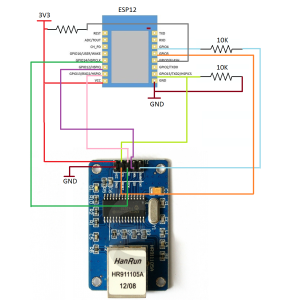
A few months back I pointed readers to an article by Frank Sautter on adding an Ethernet port to the ESP32 which I found quite interesting. It reminded me that I’d been playing around with a Wiznet wiz820io board a while back on an older PIC-based project, so I pulled it out of the parts drawer and started fiddling with trying to get it working with an ESP8266 module. There were some signs of life, but it was so flaky that I really didn’t quite know whether I had dodgy hardware or whether my graft of the ESP8266 code from the W5100 library to the W5200 library was just crap (the latter being a very strong possibility). It had whetted my appetite though, as I was looking for a means to interface an ESP module to my LAN as an ESP-Now gateway. So I ended up getting one of the (cheap) newer W5500 modules (the one with the yellow pin header and the “PWOER” LED label)‡ which are popping up all over the place at the moment at about $4 shipped (click on the picture on the right to see the full-size image of the board). The W5500 handles more sockets than the older versions of the chip and is generally recommended for newer designs (it’s a little cheaper, too).
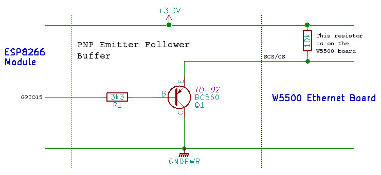
Although the W5500 needed a little tweaking to get going, there weren’t any serious issues with either the hardware or the software and it didn’t take too long to get it working. One issue (which is actually an ESP problem, not a W5500 one) is that the chip-select for the external SPI is actually routed via GPIO15 and, as we pretty much all know from experience by now, that’s one of the “magic” pins at boot-up/reset which changes the way that the ESP8266 behaves. In fact there’s a pull-up resistor on the W5500 (and, as far as I know, all of the other Wiznet modules) CS line which will cause the ESP to drop into programming mode if the W5500 CS line is simply connected directly to GPIO15. The solution to that is quite easy — put a PNP transistor buffer (configured as an emitter follower) between the two. Because of the pull-up on the W5500 board, you don’t need an emitter resistor, but you do need to add a base resistor of somewhere in the region of 3k3 between GPIO15 and the transistor’s base (and the collector of the transistor goes directly to ground). Any small-signal PNP transistor, such as the BC560 or 2N3906 should work in this situation; it’s not that critical. This fix should work for pretty much any SPI connected peripheral board …but you might have to add the emitter resistor if the target board doesn’t already have a pull-up.
The second hardware requirement is that we need to dedicate another, non-SPI GPIO as a reset driver for the W5500. On my test board I used GPIO5. This allows us to hold the W5500 in reset until the ESP has completed it’s own housekeeping and is ready to bring up the network connection. So, with that addition, the pin connects between an ESP8266 and the W5500 are:-
The pin numbering for the NodeMCU boards is given on the left, with the standard ESP8266 GPIO numbers in the centre column. In addition to the data pins shown above, you need to connect ground and either +5v -or- +3v3. The W5500 board has its own, on-board voltage regulator, so a +5v supply is okay, but sharing a 3v3 supply with the ESP8266 is a more likely scenario in our case (the data pins on the W5500 are 5v tolerant, by the way).
On the software side, I ended up using the Wiznet Ethernet Library for the Arduino 1.5.x IDE. It hasn’t been updated in a while …but the last updates were to add the ESP8266 hooks into the code. There are good instructions in the README.md file on how to install and use it, but –don’t– uncomment the “#define WIZ550io_WITH_MACADDRESS” line referred to in those instructions. The normal, cheap W5500 boards do -not- have a built-in MAC address and you must set one manually in software before you can use them.
All in all, it really was quite easy to get the W5500 ethernet board not just connected to my LAN, but also talking to my MQTT broker to both publish and subscribe. Sometime in the next couple of days I’ll try to get around to sanitizing my code to the pointwhere I can throw it up on GitHub as a simple example, but even before then, I’d say this is a safe enough purchase[¹] for anyone who wants to muck around with a wired connection to their ESP8266; you’re not going to break the bank if it doesn’t work as expected.
[¹] – Careful though! If you’re reading this in mid February, it’s Chinese new year, so everything will be closed down for the next week or so …even longer delays. 😦
[‡] – Link provided as a convenience. This is where I bought mine. I have no relationship with this seller, other than being a satisfied customer.
Frank has detailed the connections for his adapter board and included a nice bottom view (left), so that it should be fairly easy to duplicate his build. The LAN8720 boards themselves are currently available on eBay for about $3 each.
I use Unix™-like systems everywhere (I’m not going to get into a religious argument about this …I’ve been using various sorts of Unix for dang-near 40 years now and I just never quite got the hang of the GUI paradigm, so call me an old fart if you like; the moniker fits quite well 🙂 ). Recently I’ve replaced a few of the bigger, more power-hungry boxen around the house with ARM boards, which are inexpensive to buy and very cheap to run. Some of the Linux offerings (Armbian, Debian, Ubuntu-core and the various siblings, family and friends) are doing an amazing job of keeping up with the ever-changing, disparate array of hardware coming out of the Middle Kingdom (and FreeBSD isn’t far behind), so using these tiny boards as headless servers is quite viable nowadays.
Recently I bought a Nano-Pi M1 (plus 3D printed case) from the FriendlyARM on-line shop, with the intention of pressing it into service as a 24×7 web-cam support machine and general anything-else-I-can-get-to-run-on-it server. As an ESP8266 user, MQTT was one of the leading candidates in the “anything-else” category. Well, the good news is that it’s really not that difficult to get a distribution to run on one of these $11 boards. FriendlyARM do a lot better than some of the other manufacturers in making relatively up-to-date releases available from their web site and again, unlike some of the others, the choice of working distributions is actually greater than just one.
While I still haven’t got the web-cam up and running (anyone want to recommend a decent, cheap camera with reasonable resolution for landscape shots?), I have had a lot of fun playing about with this small board and trying out the various flavours of Linux available for it.
Having mentioned the Nano-Pi M1, I have to say that it is not thesubject of this post, though. While browsing my normal favourite collection of sites over breakfast this morning I came upon this little beauty (courtesy of CNX-Software …one of the better sites for cutting-edge info on embedded systems).This is the new, NanoPi NEO from FriendlyARM; the latest stable-mate to the NanoPi M1 (and for that reason, I have a quite reasonable expectation that this board will have good support from day-1 …and as my mouse hovers over the “Add to Cart” button, I hope that FriendlyARM won’t prove me wrong).
This tiny board (40mm x 40mm) has 100Mb ethernet, a USB-2 port (with two more ports available on header pins), a micro-USB socket for power and data, a Micro-SD card socket, a 36-pin header for GPIO (which includes I2C, UART, SPI and general I/O pins) all driven by a quad-core Cortex A7 running at 1.2GHz and 256MB of DDR3 RAM (512MB of RAM for an extra $2).
Before I get screamed at, I need to qualify that price and tell you that the last time I bought anything (the M1) from FriendlyARM, the postage was $10 (via DHL to most of the world, so reasonably speedy), so you need to add that into your budget. As far as I can see, there’s no case available yet (Update:- Just heard back from FriendlyARM that the case is in the works and should be available towards the end of this month …July 2016).
Update:- It looks as though FriendlyARM have changed their shipping options. When I went to “checkout” this time, the cheapest option was plain old “China Post”, with Fedex just a couple of dollars extra and the DHL/TNT option a few dollars more.
Update:- I mentioned in the original version of this post that it might be worth adding FriendlyARM’s $1 heat-sink to your order. Better hold off on that for the time being. The processor on the NEO is on the bottom of the board and we still have no idea of what the case is going to look like. Oops!
It’s going to be hard to beat this as an off-the-shelf, ethernet-connected, low power (as in watts used, not computing power) MQTT/DHCP/DNS server for your ESP8266 network.
Last word… for GUI-centric people, please do note that there is no video output connector on this board; it’s serial-console only.
Just a couple of hints on compiling Cicero’s ethernet package under BSD/Linux.
Wirewrapped ENC to ESP Connections
Updated:- Scroll down to the bottom for more details on the hardware connections.
First, the default settings in the GitHub repository source are for a Windows configuration, so if you’re a Windows user, just go ahead and type (or whatever it is you folks do) “make” and you should be all set. For those of us using BSD’s or Linux, there are a couple of extra steps before we get there.
The top-level Makefile
In the main Makefile in the esp_end28j60 directory, we need to update the paths to the Xtensa toolchain to match your machine.
At around line 15, at the top of the Makefile, locate the line starting “XTENSA_TOOLS_ROOT ?= ” and change the path to suit your specific installation. As an example, my modified line looks like this:-
Next, just a couple of lines down, locate the line starting “SDK_BASE ?= ” and change that one to match the location of your SDK (which must be at least 1.5.0, by the way). As an example, my modified line looks like this:-
SDK_BASE ?= /opt/Espressif/esp_iot_sdk_v1.5.1
Next, again just a couple of lines down, look for these two lines and update them, too:-
The first part is now complete, so save your updated Makefile, but don’t type “make” just yet.
The libesphttpd Makefile
There’s another Makefile hidden in the libesphttpd sub-directory, so cd ./libesphttpd and update the XTENSA_TOOLS_ROOT and SDK_BASE lines to match the ones you did in the top-level directory two minutes ago (there are no ESPTOOL or ESPPORT settings in this one, though).
Okay, save that updated Makefile too. Just one more file change to make…
The mkespfsimage Makefile
Change directory into a sub-directory of the current, libesphttpd, directory:-
cd ./espfs/mkespfsimage
We don’t have to edit any files here, as there’s already a Linux variant of the makefile available (it’ just that the Window’s variant is the default), so…
mv Makefile Makefile_ORIG
cp Makefile.linux Makefile
The PATH setting
There’s just one more thing we need to do. One of the things which esptool does is to try and run the command xtensa-lx106-elf-readelf in order to figure out the structure of the elf binary before loading it to the ESP8266. Because there’s no universal standard for the xtensa toolchain installation, we need to tell esptool where to find the binary on your specific machine. Luckily, this is very easy (no editing involved). Just add exactly the same path which you used to update the Makefile XTENSA_TOOLS_ROOT entry to your own PATH environment before running make. Again, in my particular case the command to do this would look like this:-
(everything after the colon should be specific to your own installation).
Now we’re ready to build. Type make and you should see some fairly normal looking compiler messages and then after a couple of minutes you’ll end up with brand, shiny, new binaries in the firmware directory.
The second make
Okay, I admit it, I forgot this (and then sat there wondering why the ENC was obviously working, but only returned 404, “Not Found” errors).
Once you’ve done that initial make, you also need to load the firmware into the ESP. That’s just a simple make flash, which I would guess most people are familiar with. However, this application uses libesphttpd, which provides a nice little web server application (+ kittens). You must load the (compressed) html files into the ESP flash at a different location from the application code, so once your initial make flash is finished, go ahead and do this extra step using:-
make htmlflash
…it only takes a few seconds and your user experience will be all the better for it. 🙂
Troubleshooting
If you see messages along the lines of:-
c:/Espressif/xtensa-lx106-elf/bin/xtensa-lx106-elf-gcc not found
…you’ve missed one of the Makefile updates (note the Windows “c:” drive selector at the beginning of the message). Go back and verify your edits again.
If you see the following error:- make[2]: Entering directory `/home/gaijin/ESP8266/esp_enc28j60/libesphttpd/espfs/mkespfsimage'
make -C mman-win32
make[3]: Entering directory `/home/gaijin/ESP8266/esp_enc28j60/libesphttpd/espfs/mkespfsimage/mman-win32'
gcc -o mman.o -c mman.c -Wall -O3 -fomit-frame-pointer
mman.c:2:21: fatal error: windows.h: No such file or directory
compilation terminated.
…you haven’t managed to change the mkespfsimage directory Makefile from the default Windows version to the Linux version. Go back to that directory and try that part again.
If you see the message:-
Error calling xtensa-lx106-elf-readelf, do you have Xtensa toolchain in PATH?

make: *** [build/httpd.out] Error 1
…you failed to add the Xtensa toolchain bin directory to your PATH. Check it with:-
echo ${PATH}
and verify that the path to the bin directory exists and is correct.
Note on the hardware shown above
As you can probably see from the photograph in the intro, this project was slapped together fairly quickly using one of the AI Thinker “Yellow” development boards. There are absolutely no hardware changes to the board at all. All of the LEDs are still in place (including the big, RGB one) and the board is still being run from the 3-cell battery pack.
The connections to the ENC module were made using a manual wire-wrap tool with 8, equal-length pieces of single-core wire-wrap wire (and kept short, not just for signal integrity, but because wire-wrap wire is getting expensive nowadays!). It took all of about twenty minutes to put everything together (and most of that time was taken up with me trying to thread the dang wire-wrap tool). Anyway, the beastie worked first time and now flashes LEDs all over the shop when initializing and handling a connection. The pins on those board connectors aren’t nearly as sturdy as proper wire-wrap pins, but the technique still works well (even better for someone with steadier hands and younger eyes — see the trivia note, below) and is definitely sturdier than a plastic prototyping board with push-in cables.
And for those of you who are as colour-blind as I am, here are the pin names for the interconnects:-
ESP8266-ESP12ENC28J60
3v3 <----> VCC GND <----> GND GPIO15 <----> CS GPIO5 <----> RST (Reset) GPIO13 <----> SI GPIO14 <----> SCK GPIO12 <----> SO GPIO4 <----> INT
Note that the ENC module I got doesn’t have any mounting holes, BTW. You have to pay extra for the holes (so check the photos carefully before you order).
Trivia note – My first wire-wrap tool was part of the tool-kit given to all techies working for a very large, U.S. computer corporation …specifically for maintenance of disk drives (the backplanes were manually wire-wrapped at the factory).
I note that the current implementation only runs the ethernet hardware and not both WiFi and ethernet at the same time, so there might be some contention for resources there, but I don’t have an ENC28J60 module to test with. If you do, Mark is looking for feedback and submissions for the project, so have at it!
On a related note, has anyone tried using a Wiznet 5200 or 5500 module (such as the Wiz-820io) for a wired connection? They’re more expensive, and perhaps not quite as versatile, but there should be considerably less overhead on the ESP8266. Let us know in the comments if you’ve built (or seen) such a beastie.
“What is it?” I hear you ask. This is Mark’s ethernet enabled ESP8266. Mark (aka Cicero on the ESP8266 forum) decided that what the ESP really needed was more connectivity and good, solid, reliable wired connectivity at that. This is the result. He has connected up an ESP8266 to an ENC28J60 and apparently now has it spitting data down the wires. The idea was first floated on the forum more than a year ago by a user going by the name “April1” (which probably hints at how serious his intentions were at the time). Mark entered the fray back in November of last year when he announced his intention to give it a go. There was a brief pause (presumably while the ENC28J60 made its way from the Middle Kingdom to South Africa) and, at the beginning of January he announced that he’d succeeded in getting the two-headed micro-monster to talk to the outside world over copper.
Mark says he wrote a separate stack for the ENC based on original work here:- http://www.ulrichradig.de/ and has MQTT and the HTTPD functioning on it already.


 This is the new, NanoPi NEO from FriendlyARM; the latest stable-mate to the NanoPi M1 (and for that reason, I have a quite reasonable expectation that this board will have good support from day-1 …and as my mouse hovers over the “Add to Cart” button, I hope that FriendlyARM won’t prove me wrong).
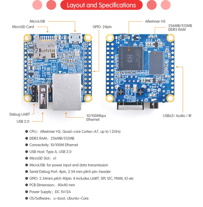

 Mark (aka Cicero on the ESP8266 forum) decided that what the ESP really needed was more connectivity and good, solid, reliable wired connectivity at that. This is the result. He has connected up an ESP8266 to an ENC28J60 and apparently now has it spitting data down the wires. The idea was first floated on the forum more than a year ago by a user going by the name “April1” (which probably hints at how serious his intentions were at the time). Mark entered the fray back in November of last year when he announced his intention to give it a go. There was a brief pause (presumably while the ENC28J60 made its way from the Middle Kingdom to South Africa) and, at the beginning of January he announced that he’d succeeded in getting the two-headed micro-monster to talk to the outside world over copper.