Towards the end of last year, Christian Baars integrated GPS-as-a-sensor support into TASMOTA with the addition of the xsns_60_GPS.ino file and ancillary code. You can now easily attach a cheap GPS unit to your ESP8266, although just exactly how to connect it and how to communicate with it may not be immediately obvious.
In this two-part series,we’ll look at some of the issues influencing Christian’s design choices before getting down to the nitty-gritty of physical connections, TASMOTA configuration and (finally) uses.
TIP — Before we start …if you have a new GPS module‡ which you’ve never used before, plug in the antenna and connect it to a 3v3 supply while you’re reading the rest of this article (it’ll save you a little bit of time and perhaps some frustration, too). You’ll notice that the LED is off when it’s first powered-on, but after a while (and it could take up to thirty minutes) it will start flashing at 1Hz. This is letting you know that it has acquired signal from multiple satellites and is now ready to send data.
BACKGROUND
First of all, just a tiny bit of background on Christian’s implementation. He is using the u-blox binary format (“UBX”) to transfer serial data from the GPS module. GPS modules from most suppliers, including u-blox, normally come with ASCII format (“NMEA”) data transfer enabled by default, but this format produces long, fairly verbose messages which are not particularly well suited to the ESP8266’s limited memory and single core processor (remembering that the CPU must attend to WiFi housekeeping tasks on a regular basis). To give TASMOTA the space and time to run its own tasks, Christian initializes the GPS board to use the short-form UBX binary data transfer instead. Unfortunately, there’s a catch — not all GPS modules will support the “UBX” native protocol which this implementation requires. As far as I know (from reading the u-blox web site), it seems as though the majority of modules for sale on Alibaba, EBay or Aliexpress are probably fakes in one way or another (older modules being labelled as newer types, or just plain knockoffs with no u-blox chips in them), so it’s no surprise that a lot of them don’t speak the UBX protocol.
My own experience pretty much mirrors this. Across three different modules, I have one (blue PCB. four-pin connector) which works with NMEA (the most common protocol), but not with UBX,  a second (red, narrow PCB, five-pin connector, with PPS¹) which just didn’t work at all and, lastly, a (black PCB, five-pin connector, with PPS) board marked as “WAVGAT NEO-6M” which does actually work using both NMEA and UBX protocols. None of these modules pass the u-blox label test . The WAVGAT module came from the WAVGAT Aliexpress shop though, so if nothing else, they may be more consistent than oddball modules from oddball suppliers (please treat this as a comment, not a recommendation). Christian mentions in the header notes of the xsns_60_GPS.ino file that in addition to a (genuine) u-blox NEO-6M, the Beitian 220 module has also been proven to work.
CONNECTIONS
Okay, so now we know that why not all GPS modules are compatible with this TASMOTA addition and why that is, but how do we connect up our module to see whether it works or not? The first thing you need to know about the connection is that serial communication with the GPS module from the ESP8266 is via the TasmotaSerial library (a TASMOTA-specific software-serial implementation) and not the ESP hardware serial port. This means that, excluding the usual suspects of GPIO-15, and GPIO-02, we can connect to just about any available pin. I’d recommend GPIO-12 (D6 on most ESP8266 boards) to the TX pin on your GPS board and GPIO-13 (D7) to RX on the GPS board. 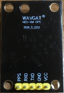 Note that it is very, very easy to reconfigure your ESP8266 (through the TASMOTA web interface) to change these pin settings, so don’t worry too much about mixing up TX and RX …it won’t hurt either the ESP or the GPS. Finally, you need to supply GND and 3v3 connections to the GPS board (do be careful with these… there doesn’t seem to be too much consistency between the different GPS makers when it comes to positioning the power connections). Those four connections are all we need (the current implementation doesn’t use the PPS signal).
Next comes TASMOTA. I’m going to assume here that you’re familiar enough with it to be able to flash a binary to your ESP8266 (and if you don’t, there’s a ton of documentation on the web site). If you’re comfortable building TASMOTA from source, then you should build with your normal “my_user_configs.h” file, but uncomment:-
- . #USE_GPS
- . #USE_FLOG
If you’re more comfortable just flashing a pre-built binary, you can download an 8.1.0.9 version built with just the GPS/FLOG defines (otherwise bog-standard “tasmota.bin”) from this link (it’s the “tasmota_GPS.bin” file). Note that it is an unconfigured binary (just like you’d pick up from the normal TASMOTA release site) and will need to be configured from scratch on your network. Please also note that the source server is using HTTPS protocol, so it is not suitable for an OTA update pull …you’ll need to download the binary file and then use the “manual upload” method (assuming your ESP is already running a fairly recent version of TASMOTA). There’s also a “minimal.bin” firmware image on the same server, but you can just as easily use the minimal image available on either the main release page or from Andre Thomas’ excellent thehackbox.org site (which is an OTA source).
This is part-1 of a two part series. Click here for part-2.
FOOTNOTES
¹ – PPS = Pulse-Per-Second.  This signal is used to synchronize the time data output – the hardware equivalent of “At the tone, it will be 3 AM, exactly“. All of the u-blox modules which I have (including a USB dongle) have PPS outputs from pin-3 of the RF module, but many modules connect it to an LED as an activity/lock indicator. However, you can easily add a PPS feed to your micro by simply adding a 220Ω resistor on the RF module side of the 1k LED current limiting resistor. Click on the photo to the left and zoom in on the bottom, L/H corner to see where the resistor is connected. Note that this module only has a four pin connector (at the top, centre of the board).
† – GPS modules can generally be configured to emit only those “sentences” of NMEA data which you specifically want, however it is still long-form, human readable data, compared to the UBX binary format.
‡ – When you first connect a new GPS module to power, nothing appears to happen. This is because the module needs to receive a certain amount of data from satellites before it can determine the current time and it’s own location. This can take up to thirty minutes in some locations. Once the module has downloaded enough data to initialize, the “PPS” LED will start flashing (even if there are no serial data connections). The data received on this initial “cold start” is automatically saved by the module itself to battery-backed memory, so on subsequent power cycles the start-up sequence will be much shorter.

[…] автоматизации, теперь также поддерживает GPS. Pucebaboon испытал устройство и поделился своим опытом после того, как GPS-координаты появились в […]
LikeLike
[…] It is these evening spikes I wanted to investigate, not the normal levels, so I have been trying to map out where they happen. I used a few electronic components, the main one is a plantower PMS7003 particle counter. This is relatively cheap (about €20) and sucks in a measured amount of air and uses a small optical sensor to count the particles and classify them into different sizes, it then works out what that amounts to by weight. The next component is a GPS module (€10ish), so I know the position where each particle reading was taken. These components were put on a prototyping plugboard with a microcontroller (any ESP8266 board will do, they cost from about €5) running Tasmota firmware that supports GPS and the sensor. […]
LikeLike