For the last in our current series of updates, we’re going to modify the board to make switch K2 into a mode control button. Pressing the button during power-on will initiate a simple light show (it’s going to be very simple …there are only three LEDs).
Switch K2 is the one closest to the LEDs and we’re going to wire it up to GPIO4 on the ESP module. If you recall our previous instalment describing the rework for switch K1, you’ll remember that we already added the 22K pull-up resistor for K2 at the same time, so this final bit of rework is simply adding one wire. The photograph shows the routing for that wire, down the side of the original jumper block and then skirting K2 itself to connect to the pin on K2 which is closest to the corner of the PCB (the bare wire on the other side is the leg of the pull-up resistor). With the previous experience of adding the LED and K1 wires, this last one should be a breeze. The GPIO pin is on the side of the ESP module which is closest to the switch and soldering to the pins (at both the ESP and K2) is easier than trying to tack down to the QFP pads (without bridging them). If you route the wire close to the jumper block you’ll only need a couple of right-angle turns and you’ll leave the area around the LEDs clear of any visual obstruction. As with the previous mods, hold the wire down to the PCB with super-glue or melted hot-glue at several points along the run.
That was easy!
The updated code for the K2 “mode” switch is already available in the GitHub repository. The code changes the power-on behaviour to add a 3-second delay (with a prompt squirted to the serial port) to allow the user to press switch K2 to go into “blinkenlights” mode. The ESP will run a brief display on the LEDs and then automatically drop back into normal operating mode. The other changes are:-
- The power-on “I’m alive!” indicator has been changed to two, brief flashes of the green LED.
- The sensor-read indicator has been changed to a single, brief flash of the red LED (Note:- the red LED may flash more than once if the ESP sees bad data coming from the DHT11 and issues a re-try).
As I mentioned at the start of this post, this will be the last of this series of updates. We do have one free GPIO pin left and we do still have the beeper and its driver circuitry intact (a small miracle, given its history). However, I have to admit to having no great longing to connect the two together at this moment in time. Depending upon how the board performs over time in its primary role as a battery-operated sensor, I might decide to add the beeper functionality back in (but basically, if it continues to work without devouring too many batteries on a monthly basis, it will probably stay in-situ, as it is).
I also mentioned in a previous post that I would be using the pads freed-up by the removal of the relay and screw-down connector to add a diode (to allow the board to draw power from the 5v USB adapter), but as the batteries are holding up quite well so far (and because of the possibility of someone — me! — accidentally leaving the batteries in while the USB is connected), I’m postponing that to some, unspecified later date (a hairline this side of never), too.
Let me know how you get on with your own versions of these hardware and software mods and, if I remember, I’ll try to leave an update here every now and then to let you know how the modded T5 is holding up long term.
Update – Well, after a couple of months running this as a battery-powered sensor node I’d like to add a couple of observations. First, the battery life isn’t great. I’m using deep sleep of course, but I had trouble getting the wireless to reliably reconnect to the preconfigured access-point if I disabled wireless at start-up and only initialized it when I wanted to talk to the MQTT server (which would conserve more power). Second, the DHT11 sensor is fairly crap (as many have noted before), with occasional readings being way, way off from the previous or following measurements. I’ve recently had much better luck using a BME280 sensor unit, which also includes barometric pressure (as well as using the standard, Dallas one-wire sensors for just plain, vanilla temperature measurement). On a slightly more positive note though, the ESP8266 sensor nodes do seem to be very reliable (given a good set of batteries) and the MQTT broadcast timestamp and generation of sensor data works very well.


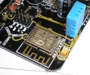 It’s starting to get a little bit crowded around that SMD capacitor, but there’s only one spare GPIO left on that side of the board anyway, so we’re not going to be adding too many more wires.